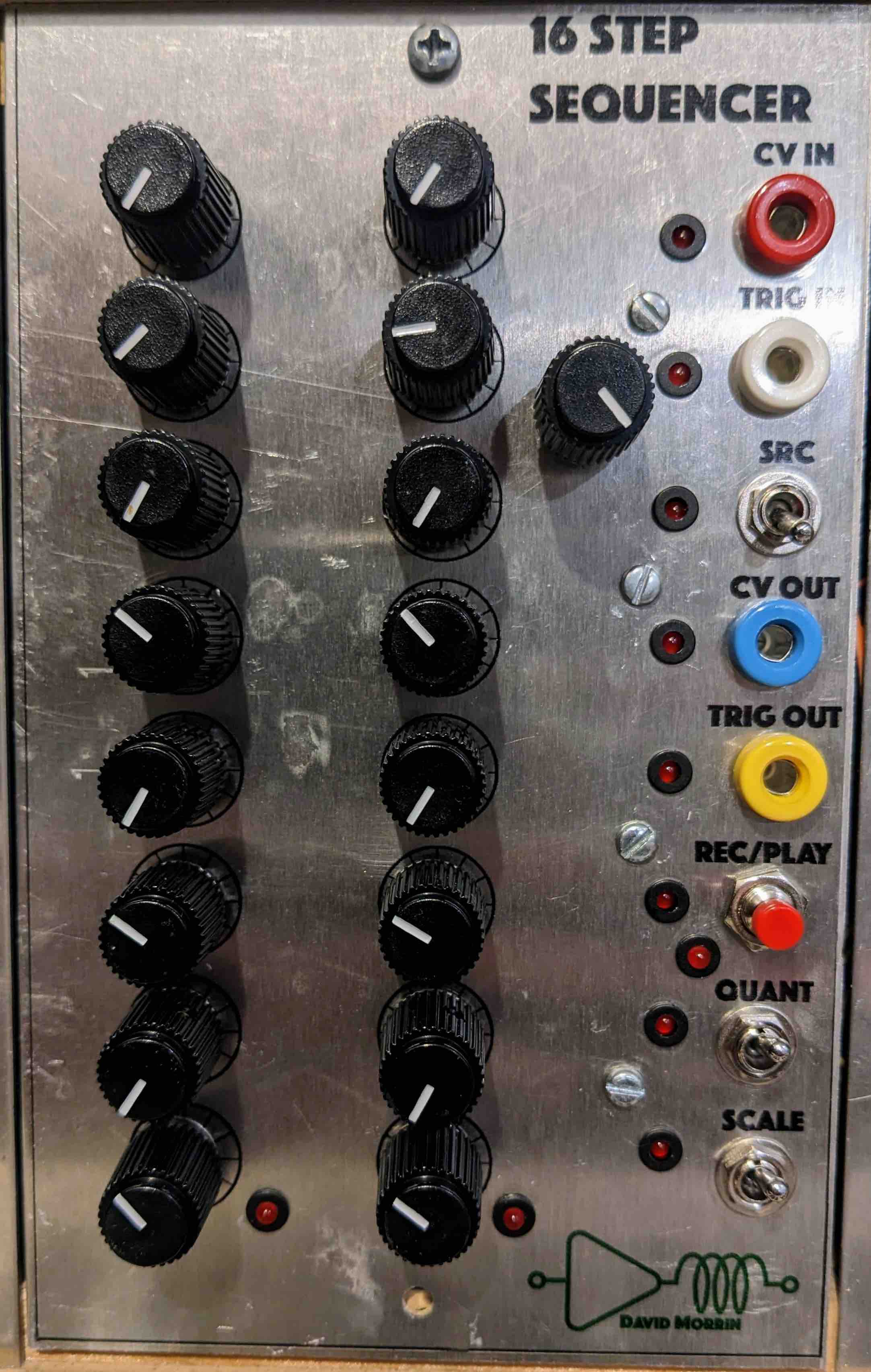
16 Step Sequencer
This sequencer is based on a Raspberry Pi Pico microcontroller. Code for the Pico is available on Github.
The original idea was to have a module that would store CV input in memory on each input trigger pulse in a “record” mode, and output the stored CV on each input trigger pulse in “play” mode. Putting a set of multiplexed pots in front of the CV input turned it into a classic sequencer. The CV source can be selected as front panel or potentiometers through the SRC switch.
The Pico and DAC run on 3.3 V, so the input and output have to be shifted and scaled to interface with the +/-10 V system. When the pots are selected, they are just hooked up between 0 and 3.3 V, so no processing is required, but the panel input has to map the input range to 0 to 3.3 V. System 0 V is shifted to 1.65 V and the system input has to compressed to fit into 3.3 V. On the output side an inverse shift and expansion can restore the compressed CV to the system level.
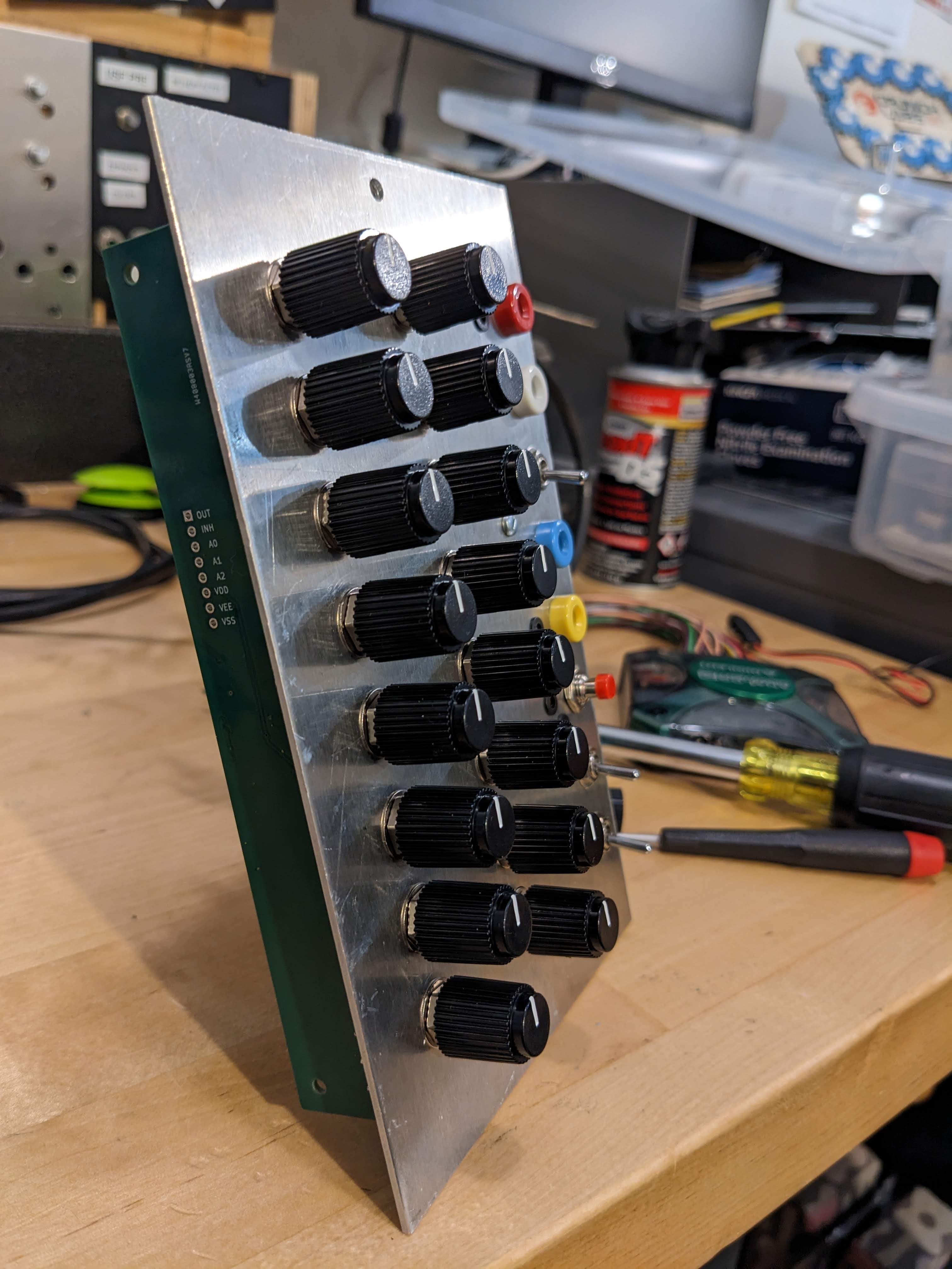
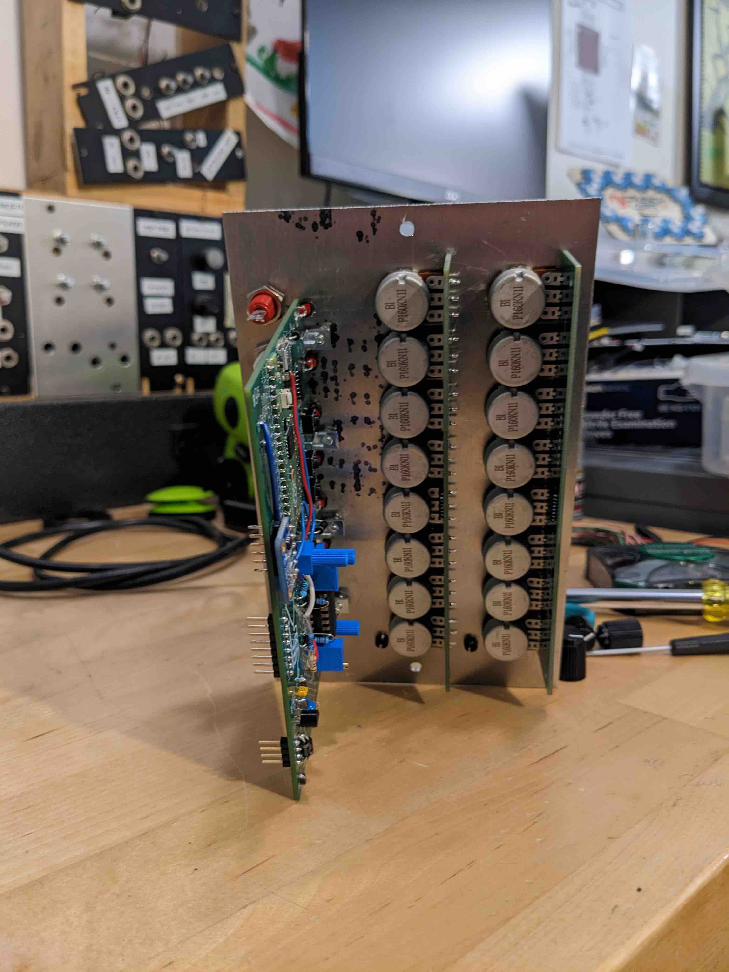
The potentiometer boards each hold 8 pots and use a CD4051 IC to route the output of a pot to the ADC input. The CD4051 has an “inhibit” input that can be used as a chip select pin. This means the system is expandable to many more pot boards, so I could have myself a 64 step sequencer if I wish, or maybe split the pots into different functions (e.g. half for CV, half for gate length).
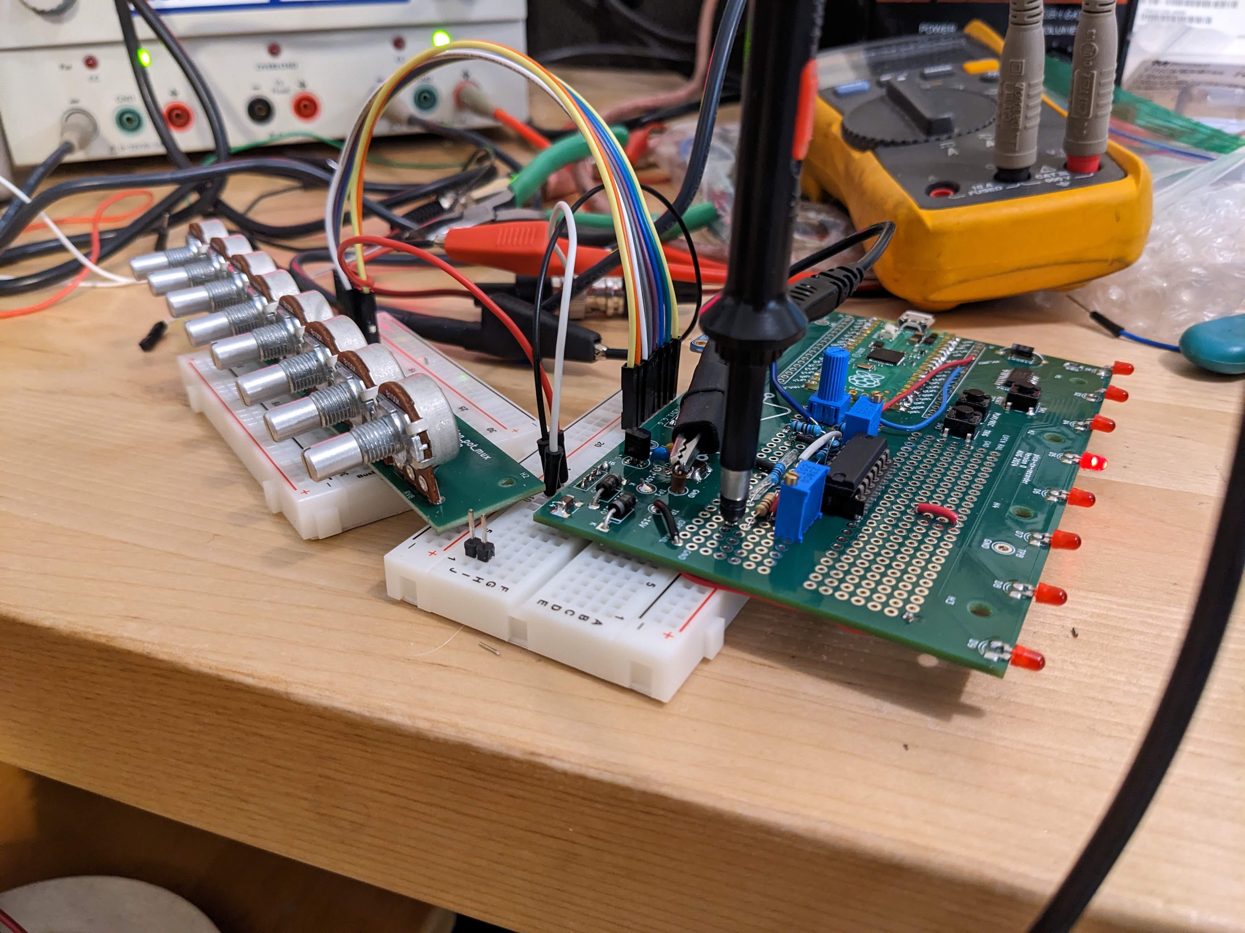
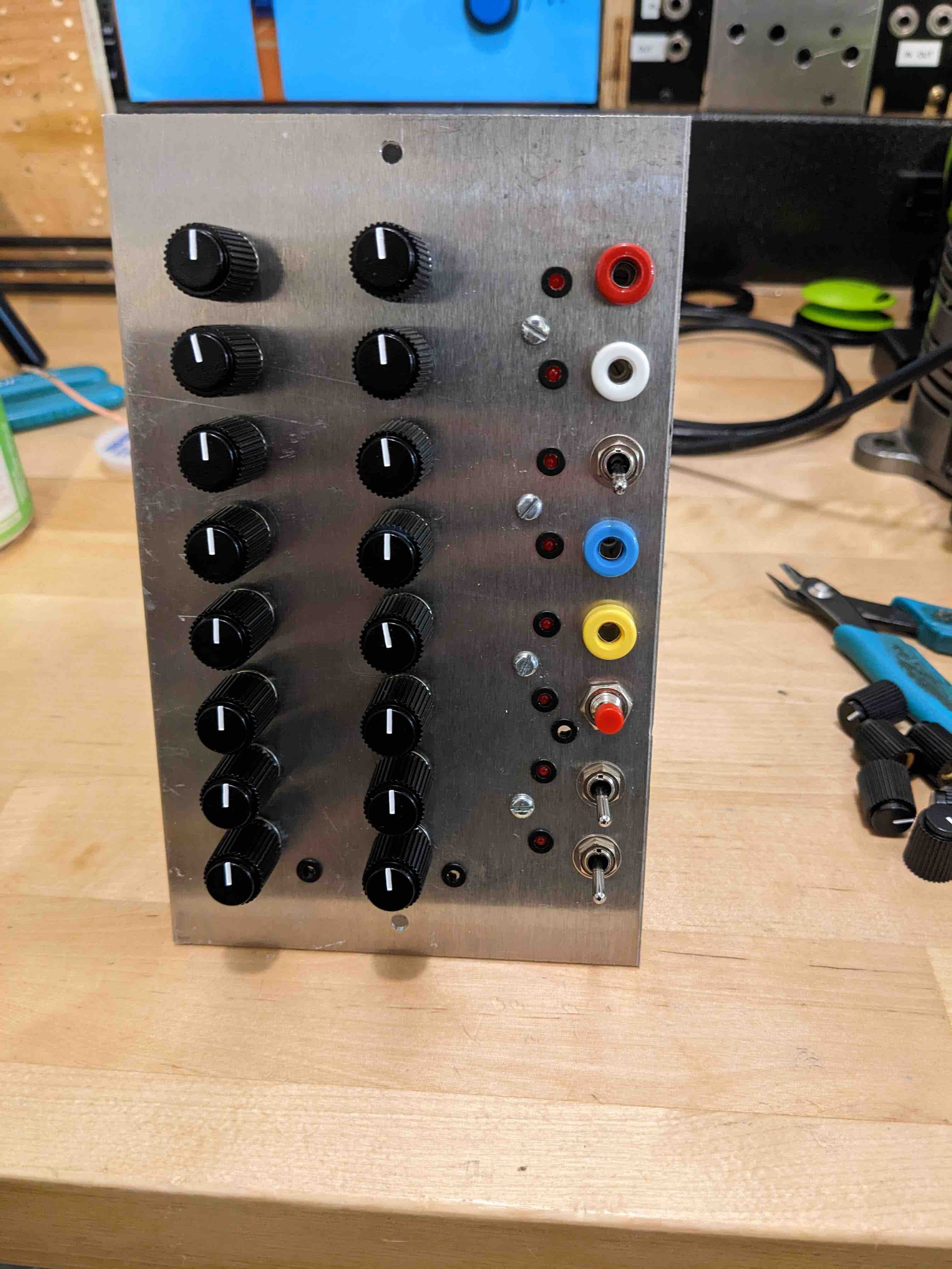
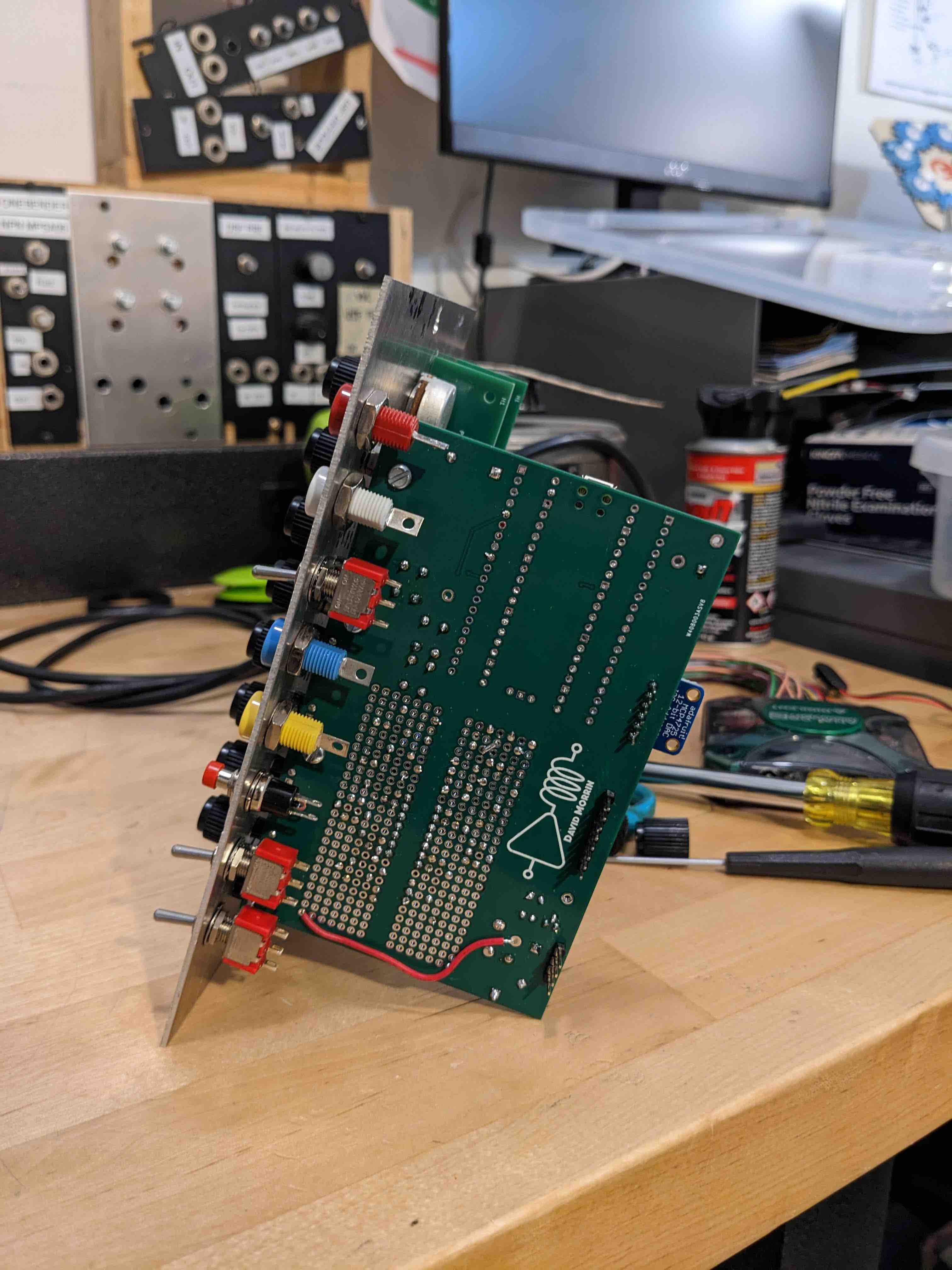
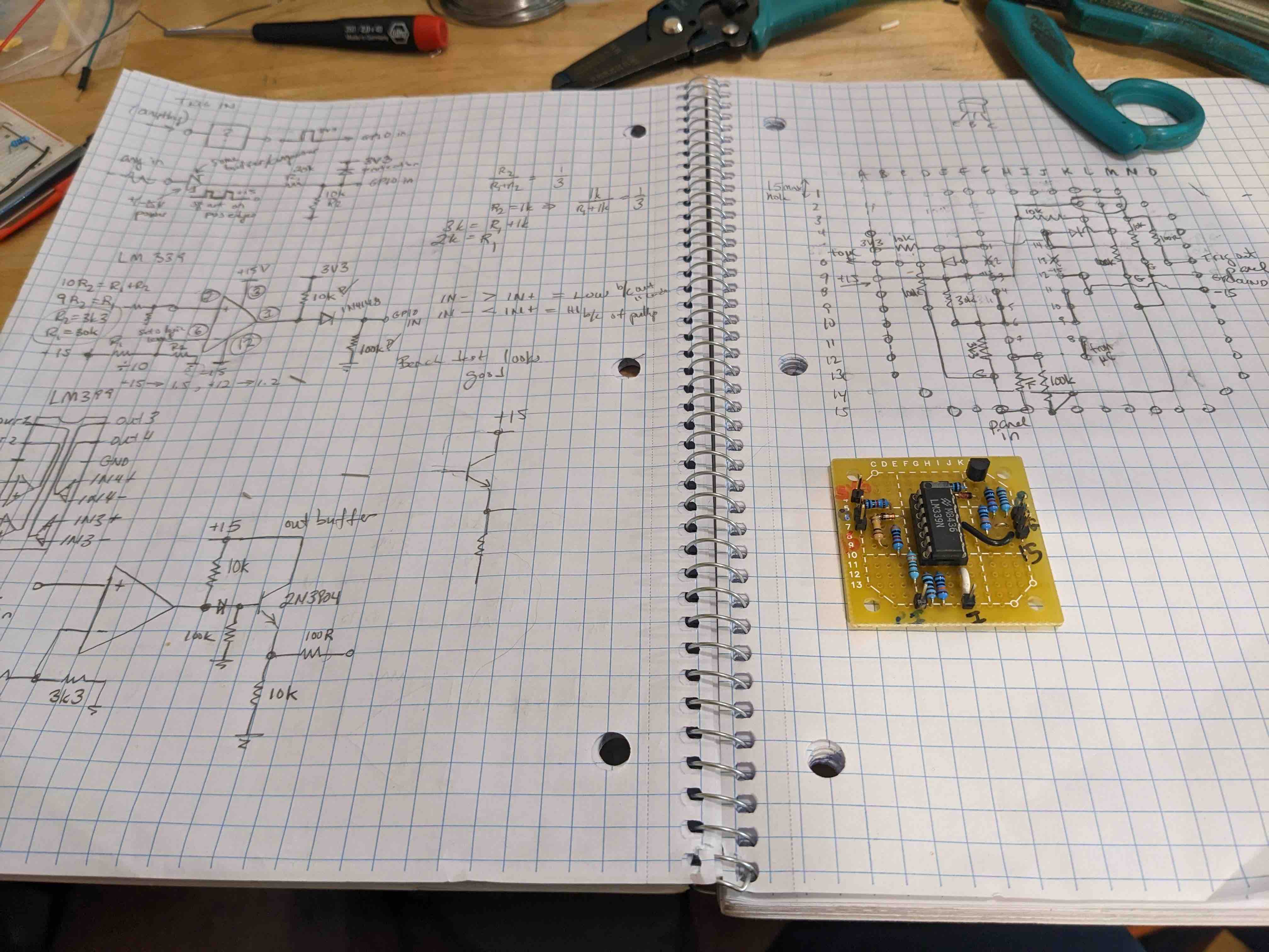
This module kicked around the workbench on breadboard for a long time without making much progress. I finally got it moving again by creating a PCB with a prototyping area, which is in the pictures below. The prototyping area got filled up with scaling circuits. I still needed to add two additional pad-per-hole prototyping boards for the trigger interfacing using a LM339 (picture below) and wiring up two pot boards (lack of pads to attach the shared connections).
A follow up version will incorporate these additional boards and scaling circuitry on the main board.
