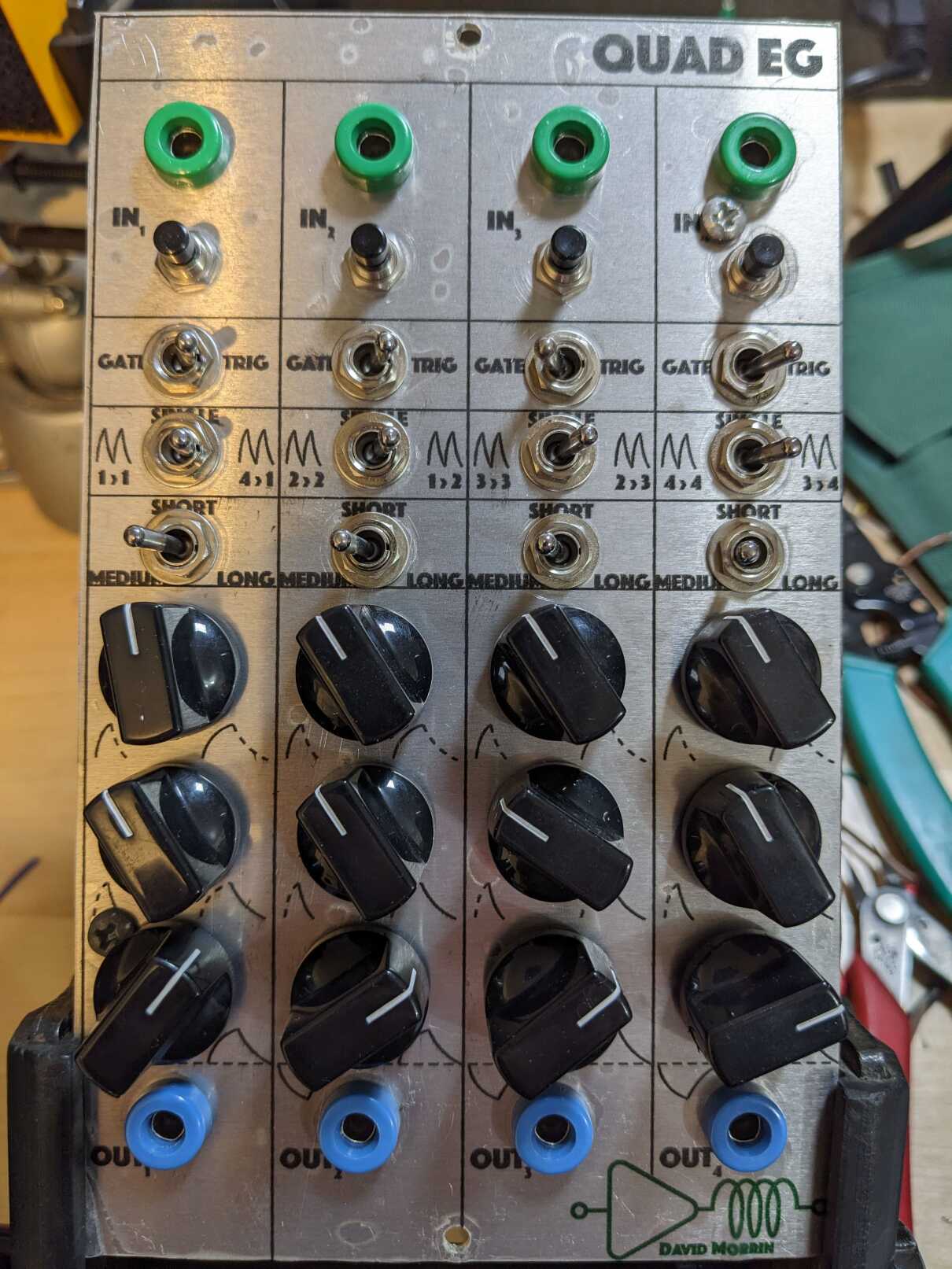
Quad Envelope Generator
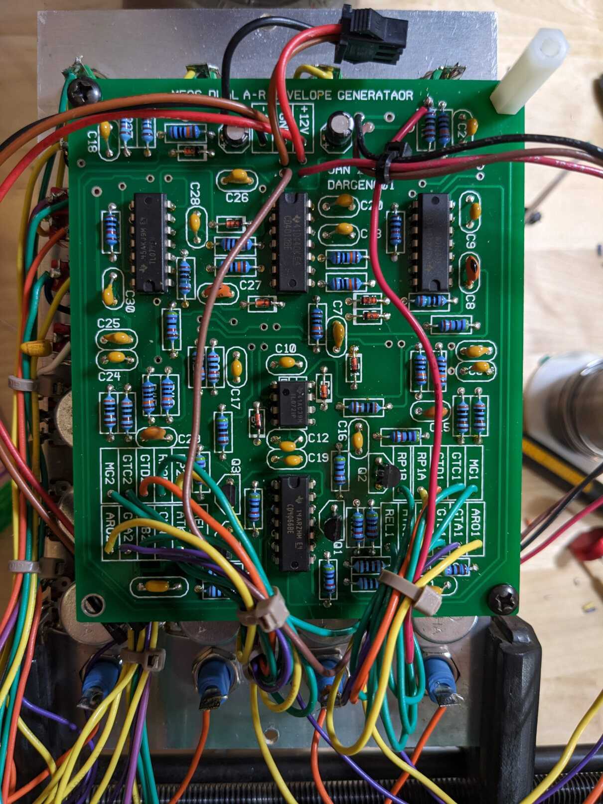
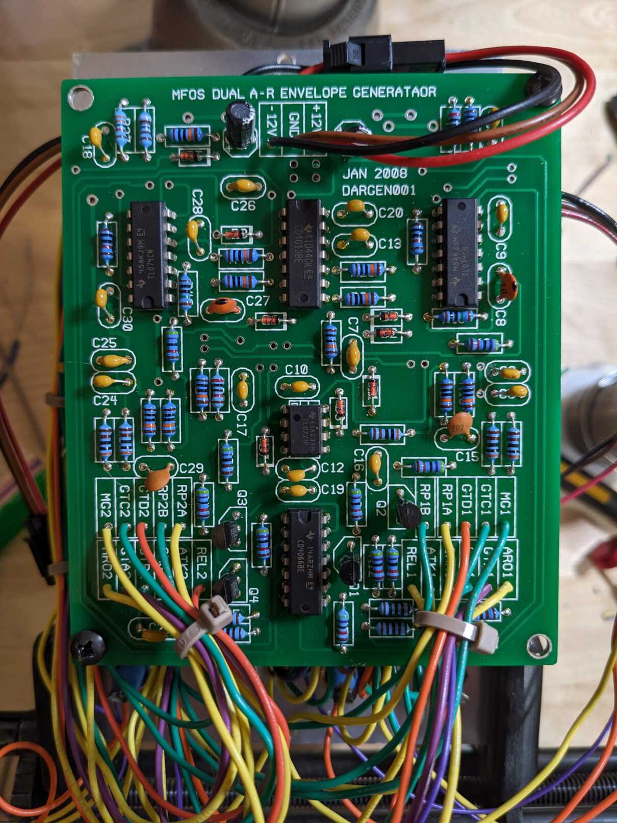
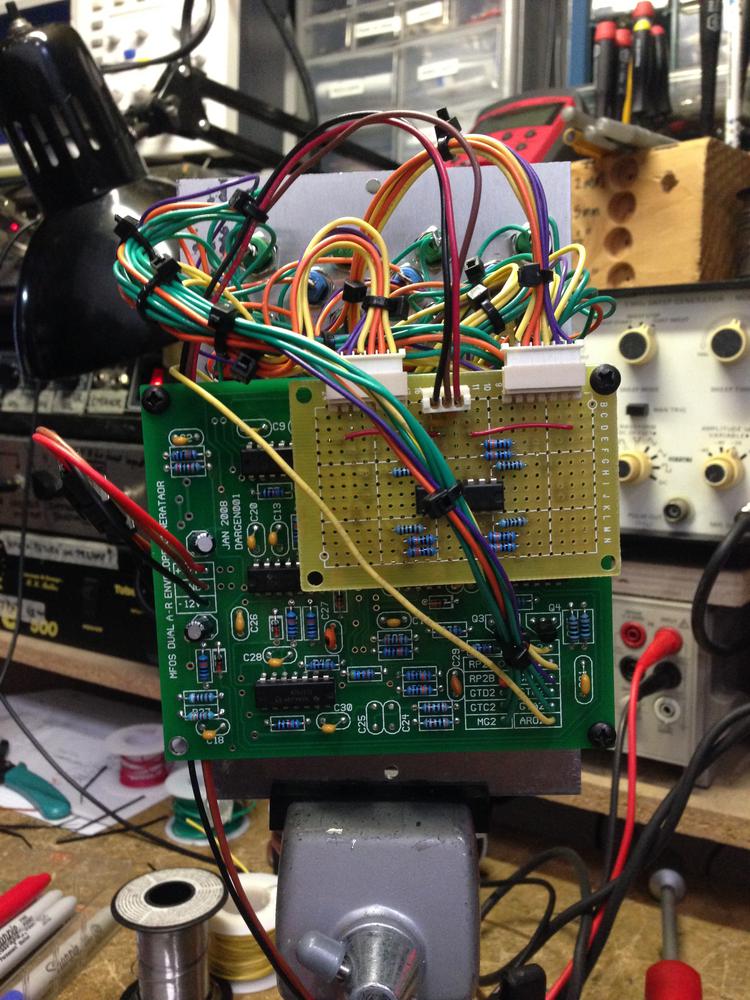
This module uses Dual AR MFOS PCBs.
Four channels of envelope generation, each channel featuring
- Gate/Trigger switch
- Repeat switch (self/chain)
- Short/Medium/Long time switch
- Attack time control
- Release time control
- Bipolar output
Chained envelopes
The stock MFOS option for self-triggering was expanded to allow chaining each generator together. The MFOS design allows you to switch-in a “envelope done” signal to the input, creating a self-triggering patch. Using a 3-way “on-off-on” switch, I added the option to patch the “envelope done” signal from the “previous” channel (channel 1 is fed from channel 4, channel 2 from channel 1, etc.) to create a self-triggering chain.
Bipolar outputs
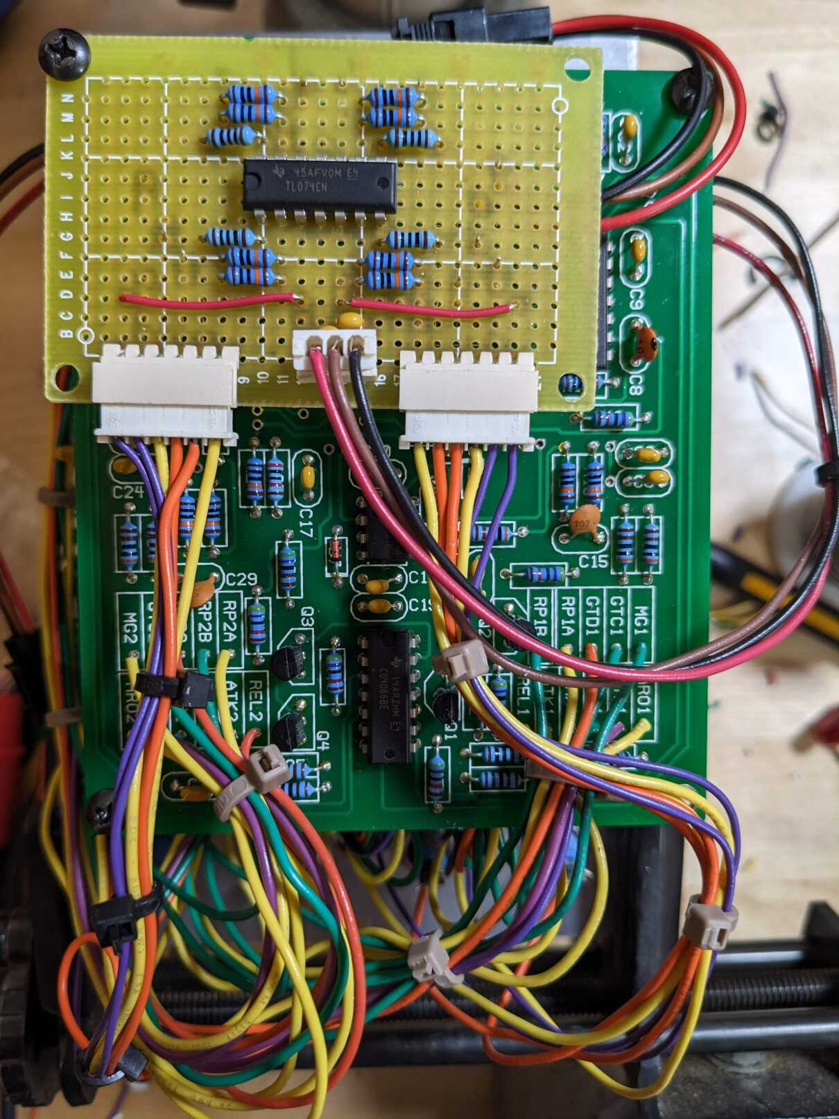
An extra TL074 quad op-amp IC replaced the original unipolar output level control with a bipolar output level control.
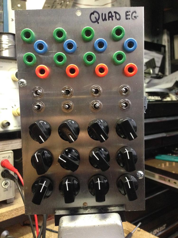
2025 update
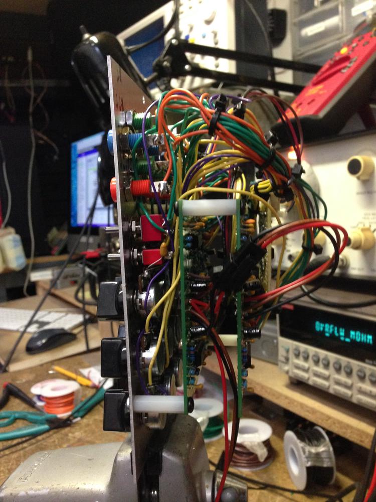
As part of my new panel graphics project, I gave this module an overhaul in 2025. The original module (seen below) was too crowded for my hand drawn panel graphics. The lack of graphics was problematic as I would forget how to use it and it made the module very unfriendly to guests.
Repeat switch
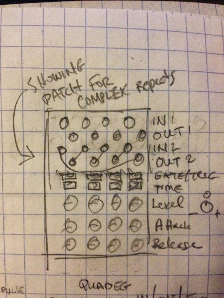
The original chaining scheme was accomplished with patching. This was a bit too open ended and just cost me 4 patch cables any time I wanted to chain up the generators. I decided to make patching easier by ditching the jacks and wiring up the chaining option to switches.
Gate buttons
With a better layout I was able to fit in the push buttons for manual gating that I deleted from the initial version.
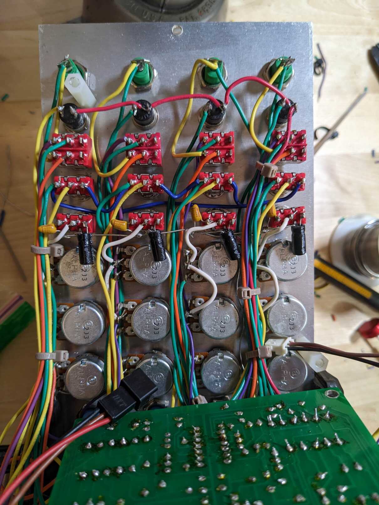
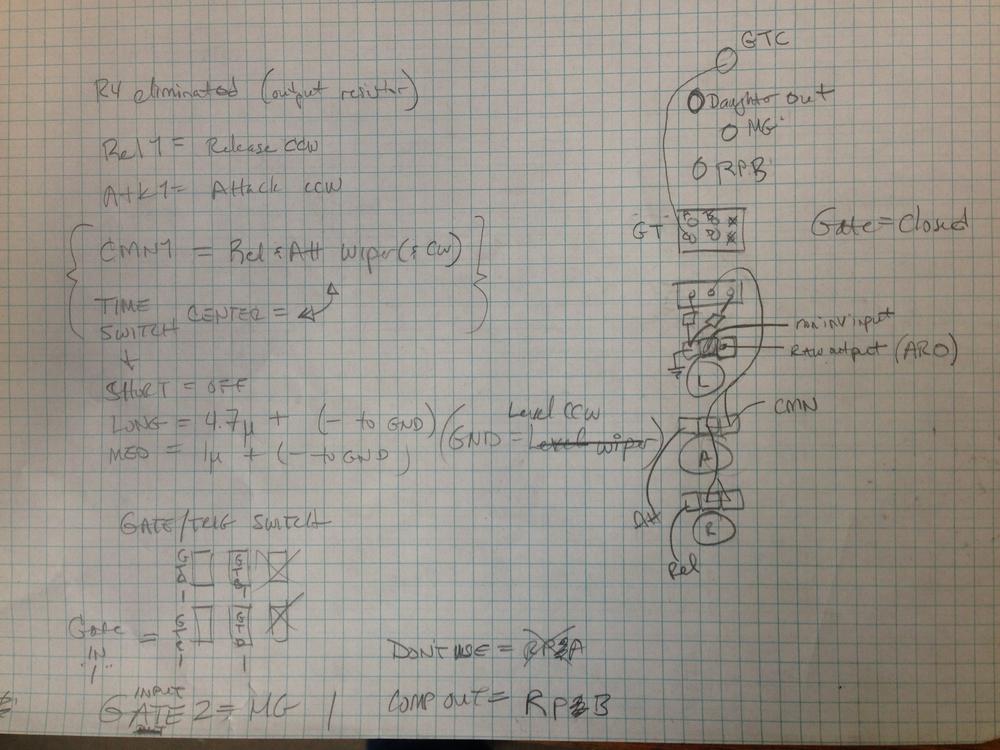
Wiring notes
Gate/Trig switch
| Color | PCB node |
|---|---|
| Purple | GTAn |
| Green | GTBn |
| Yellow | GTCn |
| Orange | GTDn |
Repeat switch
| Switch terminal | PCB node |
|---|---|
| A (Self-trig) | RPnB |
| Common | RPnA |
| B (Chain) | RP(n-1)B |
Note that the above implies RPnB is tied to two switches, it’s own channel and the next.
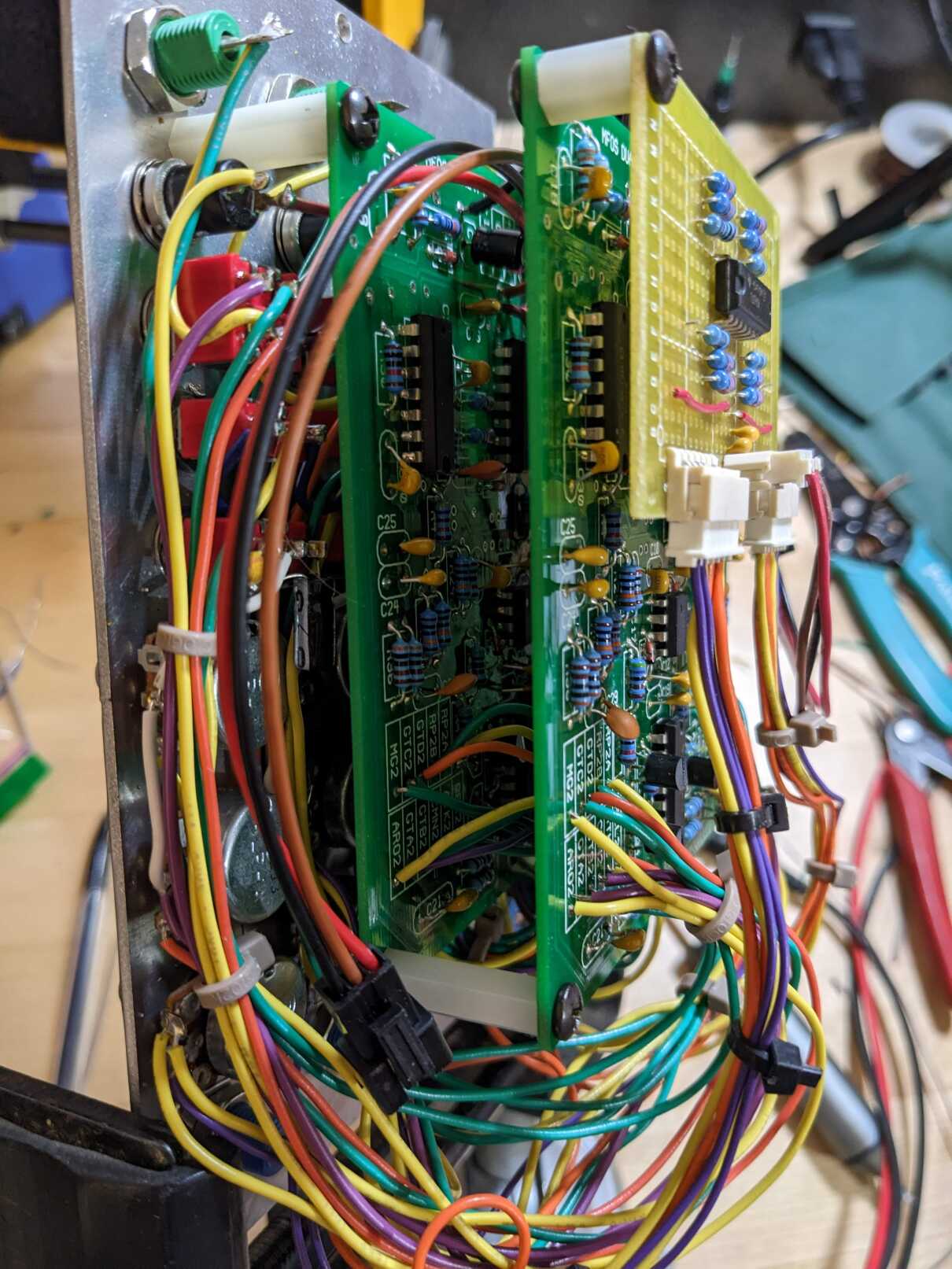
Bipolar output board
Viewed from the component side with wires exiting downwards.
Left connector:
| Wire No. | Color | Ch. No. | Function |
|---|---|---|---|
| 1 | Purple | 3 | Level ctrl wiper |
| 2 | Purple | 4 | Level ctrl wiper |
| 3 | Yellow | 4 | Level ctrl input |
| 4 | Orange | 4 | Bipolar output |
| 5 | Orange | 3 | Bipolar output |
| 6 | Yellow | 3 | Level ctrl input |
Right connector:
| Wire No. | Color | Ch. No. | Function |
|---|---|---|---|
| 6 | Yellow | 1 | Level ctrl input |
| 5 | Orange | 1 | Bipolar output |
| 4 | Orange | 2 | Bipolar output |
| 3 | Yellow | 2 | Level ctrl input |
| 2 | Purple | 2 | Level ctrl wiper |
| 1 | Purple | 1 | Level ctrl wiper |