
CD4046 Phase locked loop
The CD4046 is a small kit of circuits contained in a single package. The kit includes
- VCO (voltage controlled oscillator)
- Comparator I
- Comparator II
- Source follower (buffer, with mute control)
- 5.2 volt Zener diode (available for use as a local 5 V power node)
The VCO and one of the comparators can be connected in a loop to form a phase locked loop (PLL), but those connections must be made externally which allows the VCO to be used independently if desired.
Standalone VCO
If you just want to use it as a VCO you just need to pick values for R1 and C1 (10k and 3n3 seem to cover audio range) and apply a voltage between VDD and VSS to the VCO input pin (9).
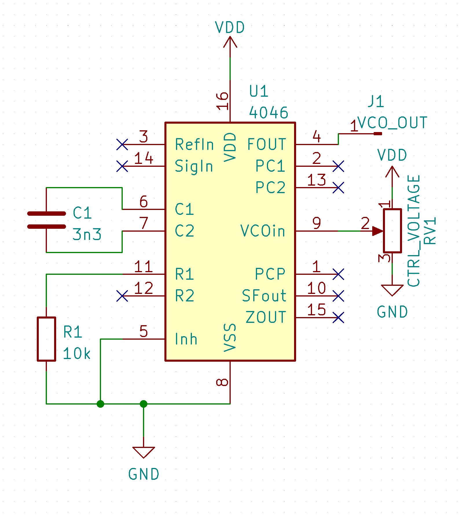
While the VCO input can be used with any voltage, the intended use is get control voltage from the comparator circuits.
Comparators
Comparators, as the name suggests, compare two things and provide some indication of whether the two things are the same or different.
The comparators on the 4046 share a common external pin to feed their first inputs (pin 14), and another common external pin to feed the second inputs (pin 3). The intention is to put the external frequency on the common pin and then feed to the VCO output to the second inputs.
The 4046 comparators provide a means to compare frequencies and produce pulses when the frequencies don’t line up.
The pulses can be integrated (i.e. low-pass filtered) into a control voltage for the VCO, replacing the potentiometer shown in the VCO standalone schematic.
Multiplication requires division
A useful application of the 4046 is frequency multiplication.
Perhaps counter-intuitively, in order to multiply the input frequency you must divide the output frequency.
To recap: we have some square wave source signal coming into the comparator circuit. This is going through our integrator to become the control voltage for the VCO.
Instead of connecting the VCO output directly to the second comparator input, the VCO output is delayed via frequency division (using digital counters) which makes the comparator output speed up the VCO.
The comparator output tries to get the VCO to run fast enough to match the input signal… thus by dividing the output you end up multiplying the input!
A simple flip-flop delay produces a frequency doubling effect.
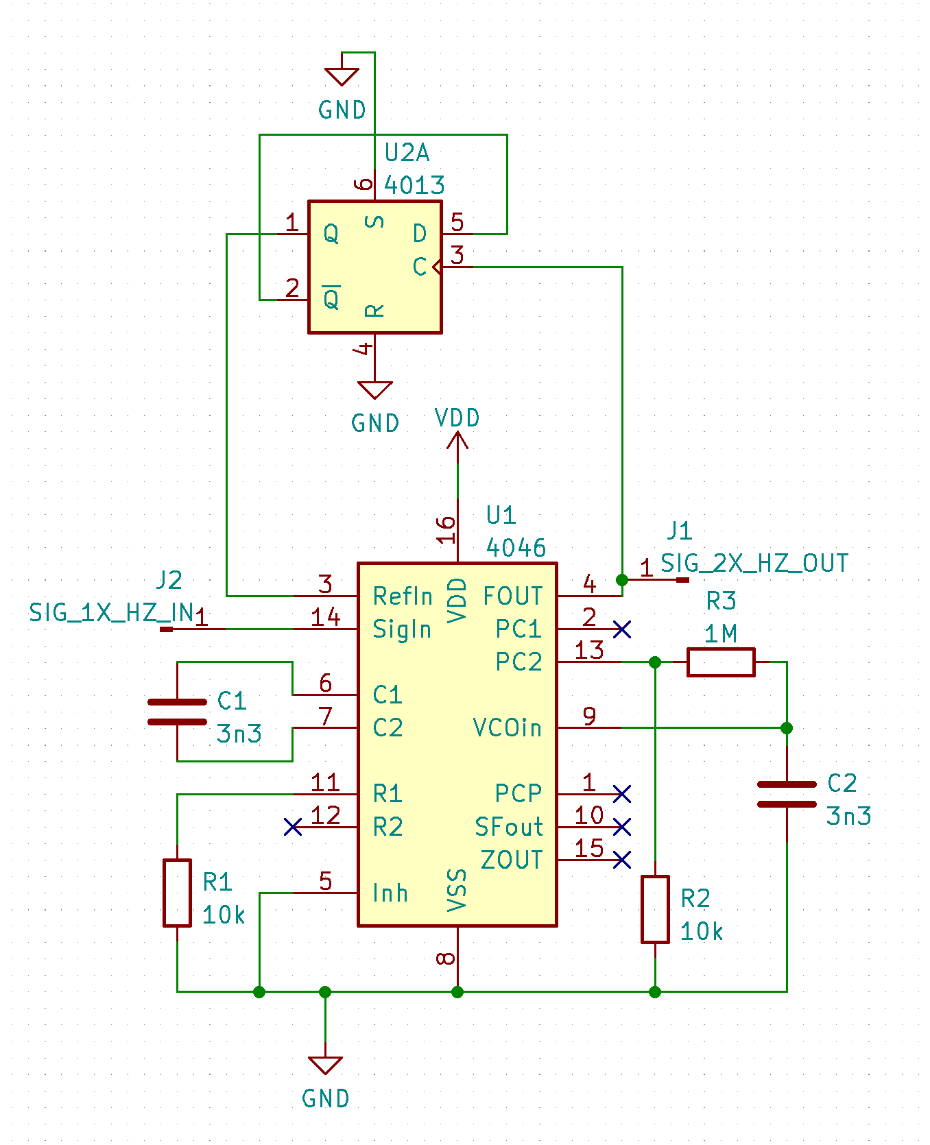
The above circuit seemed a bit jittery as I moved the input frequency around. It lost lock when I moved the frequency too low. Increasing the filter capacitor (C2) makes for a fun vibrato effect as the VCO slowly locks on. Comparator I seemed a bit more solid with a square wave input while II was able to to handle pulses.
Using digital counter ICs allows for an arbitrary (integer) multiplication.
FM Radio
Perhaps the neatest party trick this IC does is FM demodulation.
The source follower is included for this intended purpose.
The data sheet and RCA ICAN-6101 application note have the details.