
Circuits for Audio Engineers
Long ago, an audio engineer was inherently an electrical engineer. To assemble a system consisting of a high quality condenser microphone, vacuum tube amplifier, corrective equalizer, and lacquer disc cutter in the 1930s was a bit different than connecting a condenser microphone to a USB audio interface today. Our modern standards, like XLR connectors and USB interfaces, have made our systems easier to build and maintain and greatly reduced the need to dive into the science of how these connections work. While audio engineering no longer requires the electrical engineering knowledge, understanding the underlying principles can be invaluable for troubleshooting and optimizing our systems.

Consider the signal chain of microphone into mic preamp1 into an equalizer (EQ) into analog-to-digital converter. Where can we alter the frequency response of the signal?
The unit that is specifically designed for that job is the EQ. Is that the only place we can alter the frequency response?
What about the microphone? Audio engineers learn that you can select microphones and place microphones to alter the frequency response.
Even the preamp and the converter, while ideally neutral, can also have a frequency response.
How about the cables that connect the components? Can simple cables also alter the frequency response?
Cables as filters
For a motivating example, let’s consider what can go wrong with a really long cable run.

Initially you plug the guitar with a short patch cable directly into the amplifier. The sound is bright and clear.

For a myriad of reasons you may want to lengthen the cable. Maybe you’re playing a large stage and you don’t have a wireless system. Maybe you’re in the recording studio and you want to put the amp in the live room while the guitarist plays in the control room. With some adapter cables you can send the guitar signal over the studio tie lines. Unfortunately, once everything is connected and a microphone is sending the amp’s sound back to the control room, the sound is noticeably dull.
The effect is identical to adding a low-pass filter to the guitar signal, yet no such filter was added.

Experienced audio engineers will know what to do next. The guitar should get plugged into a direct inject (DI) box with a short cable. The DI box is then connected to the long cable run. At the amp end, a passive DI connected “backwards” (nominal output used as input, nominal input used as output) is placed at the end of the long cable run, and a short instrument cable is patched from the backwards DI to the amp.

The savvy guitar player may know another way to maintain a bright, clear tone despite hundreds of feet of cable. Inserting any Boss brand guitar effects pedal, even with the effect bypassed, will restore the original sound.
We seek to answer these questions:
- Why does the cable act as a low-pass filter?
- Why do the DI boxes remove the filter effect?
- Why does a Boss pedal remove the filter effect?
Introduction to circuits

After the invention of the battery2, 19th century scientists got to work hooking up batteries to various materials to see what would happen. One observation was that wires get hot. The battery is putting energy into the metal, and the observable effect is heat. Another observation is that compass needles deflect3 while circuits operate because all circuits generate a magnetic field while they operate.
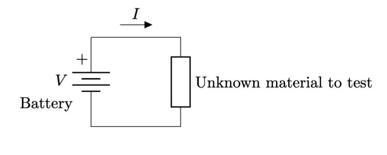
In the image above, the battery is now represented by a series of alternating lines. These represent the different metals that form a battery. We will assume that for any circuit we consider, we can always observe the electric current using a sensitive compass needle, or a modern ammeter (device for measuring current). The current is labeled $I$ for the intensity of the current (and $C$ is taken by something else!).
In summary: we apply a voltage to a circuit, usually via wires, and the response of charges racing around the circuit is called current. The current measures both the number of racers and how fast they are going. Voltage and current are fundamental quantities we can measure directly.
To follow in the footsteps of the 19th century scientists, let’s consider this simple test bench. Using our battery, we can complete a circuit with various components and we will observe the current response. We can try metals, plastics, wood, clay, etc. In each case we will note the current response: a large response for a good conductor like copper, or little to no response for good insulators like plastic and rubber.
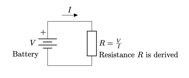
In 1827, Georg Ohm tested various cables and established resistance, $R$, as the ratio of the applied voltage to the current response.
\[R = \frac{V}{I}\]and we measure resistance in units of ohms in honor of Georg Ohm. The symbol for the ohm is $\Omega$, the upper case Greek letter omega. The relation is often written as
\[V = IR\]and referred to as Ohm’s Law. Note that resistance is a derived or calculated quantity, whereas the voltage and current are directly measured quantities.
Now that the basics of circuits is out of the way, let’s get back to talking about audio.
Audio circuits
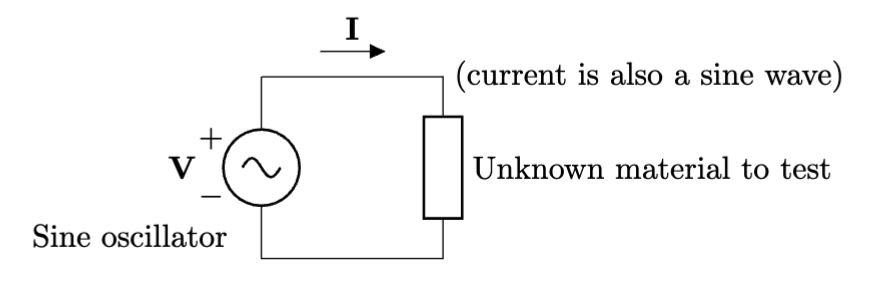
Audio engineers learn that sinusoidal waves, also known as time-harmonic, or harmonic waves, contain only one frequency and any complex audio signal can be constructed by summing (a.k.a. “mixing” in audio terminology) many sine waves.
So to replace our battery in the test bench so we can explore audio signals, we choose a sine wave oscillator. You can imagine this is pulled from a modular synthesizer.
Testing reveals 3 cases: sweep of the frequency, low to high, causes no current change, current increase, or current decrease. These are the resistor, capacitor, and inductor, respectively.
Resistors are faders
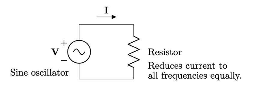
Resistors are things that follow Ohm’s Law regardless of the frequency. This means if we make a “filter” using resistors, we will affect all frequencies equally. Is that useful? Definitely: we can make faders out of resistors.
Coils are low-pass filters
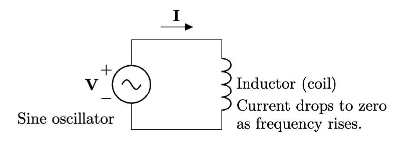
Inductors give dynamic mics and speakers their well known transducer behaviors. However, the magnetic field they store in their coils fights changes in current. This means if you try to change the current quickly (a requirement for high frequencies), the coil will resist that quick change. Eventually the resistance to a changing current is so great that the current drops to zero. It is this mechanism that makes coils natural low-pass filters.
Parallel conductors are high-pass filters
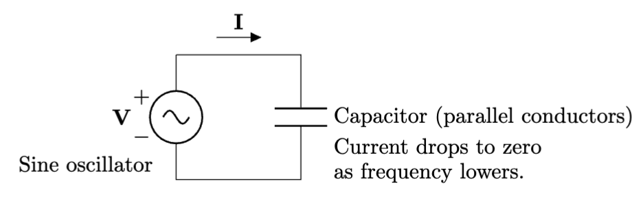
Capacitors form the transducer element used in condenser mics. In general, anywhere you see parallel conductors, you have a capacitor. The closer the conductors, and the bigger the parallel area is, the bigger the capacitance. What is capacitance? It’s the amount of charge (you can imagine electrons) that can fill up the parallel plates.
Notably, just as the symbol implies, this circuit is open to batteries, and by extension very low frequencies (think of a battery as voltage with a 0 Hz frequency). So when we test it, there is no current at low frequencies, and the current goes up and up with frequency. As a dual to the inductor, capacitors are natural high-pass filters.
Have you heard of crosstalk? Our mixing consoles are designed to only mix the signals we tell it to. If you hear a sound on a track you weren’t expecting to hear it on, that’s called crosstalk and can be caused by parallel wires becoming electrically connected through capacitive coupling.
Every signal carrying cable in the studio has at least two conductors and there is always some amount of capacitive coupling between the wires. Manufactures declare this as capacitance-per-foot or capacitance-per-meter.
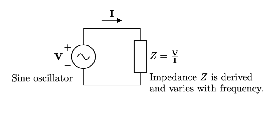
Unlike the resistance in Ohm’s Law, the inductors (coils) and capacitors (parallel conductors) vary how they respond to our sinusoidal oscillator depending on the frequency we set. We can still take the ratio of sinusoidal voltage to sinusoidal current, but we have to give it a new name and new symbol. The units will still be ohms and still use the symbol $\Omega$. The new name is impedance, with symbol $Z$.
\[Z = \frac{\mathbf{V}}{\mathbf{I}}\]The boldface type indicates the voltage and current are sinusoidal4 to differentiate from our constant battery voltage and the battery response current we considered prior.
Cables as filters, revisited
Now that we know some circuit theory, let’s examine that long cable run again.
The conductors in the cable have very low resistance, but the capacitance between the shield and the center conductor increases with each foot (or meter) of length we add. It was this capacitance that was at the heart of the low-pass filter effect caused by the long cable.
Guitar pickups are made from relatively large inductors (lots of windings). The inductance is measured in units of henries (typical inductors come in thousandths or millionths of henries) which has a strong high frequency roll-off effect, and the resistance of all that small-gauge wire measures in the thousands of ohms.
The high source impedance of the guitar pickup works in conjunction with the cable-as-capacitor to remove the high frequencies from the system.
To fix the problem, we need to somehow lower the source impedance before we try to drive the long cable. Somehow the passive DI box and the Boss pedal manage to lower the source impedance. They each work in different ways. The passive DI box uses the transformer. The Boss pedal uses the amplifier.
Transformers

Faraday and other 19th century scientists experimented with induction by wrapping coils around metal rings. Amazingly, an electric current through a wire on one side of the ring could cause another current to flow in a wire on the other side. They concluded the iron ring facilitated a dual to the electric current: a magnetic current.
Transformers allow us to boost and cut our signal voltage via a simple mechanism: the ratio of winds in each coil. This same mechanism lets us boost and cut the impedance as well.
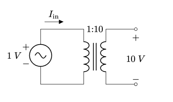
Above is a modern schematic version of a transformer. There are two coils, drawn just like the inductors we looked at earlier. Between them are two lines in indicate the ferromagnetic core. The core boost the magnetic current effect, which is essential for audio frequencies.
The ratio “1:10” indicated just above the transformer symbol is telling us the ratio of the coil windings. For every 1 wrap on the left hand side, there are 10 wraps on the right hand side. Note that we typically do not fuss with trying to draw the coil ratio in the symbol. We just draw equal coils for the symbol and write the ratio above. (In service manuals the ratio is often omitted, unfortunately.)
Let’s say the turns ratio is 1:10. This means you can put 1 volt “in” and get 10 volts “out.” What’s the catch? You have to trade current for voltage and vice versa.
Power in has to equal power out and circuit power is defined as the product of voltage and current or
\[P = IV.\]So let’s expand that for both sides with our 1 volt in and 10 volts out. Just for ease of explanation, let’s say we had 10 amps going in (that’s a lot, but it’s just to keep the numbers simple).
\[P_{\mathrm{in}} = P_{\mathrm{out}}\] \[(VI)_{\mathrm{in}} = (VI)_{\mathrm{out}}\] \[(1)(10) = (10)(1)\]Which means the current in must be 10 times the current out, or the current out is 1/10 of the current in.
\[I_{\mathrm{in}} = 10 \cdot I_{\mathrm{out}}\] \[\frac{I_{\mathrm{in}}}{10} = I_{\mathrm{out}}\]So we can trade current and voltage. If voltage goes up, current goes down. If voltage goes down, current goes up.
But there’s that other expression we had with $V$ and $I$. Let’s see what happens to the impedance.
\[\begin{align} Z_{\mathrm{in}} & = \bigg(\frac{\mathbf{V}}{\mathbf{I}}\bigg)_{\mathrm{in}} & Z_{\mathrm{out}} & = \bigg(\frac{\mathbf{V}}{\mathbf{I}}\bigg)_{\mathrm{out}} \\ Z_{\mathrm{in}} & = \frac{1}{10} & Z_{\mathrm{out}} & = \frac{10}{1} = 10 \end{align}\]So if we increase the signal voltage, we also increase the impedance. If we decrease the signal voltage, we also decrease the impedance. They go together.
Passive DI boxes are just transformers
The passive DI box uses a transformer to trade the relatively high signal voltage coming from an electric guitar and trades it for a lower impedance. The lower impedance drives long cables without losing high frequency content.
Passive DI boxes work “in reverse” without a problem because transformers do not inherently have dedicated “input” and “output” terminals: they just have two sets of coils and you can use either side as your input.
Demystifying the “hi/lo” switch
Some old microphones have an impedance switch. This switch will select between different taps on the output transformer.
Using the DI input and toggle the hi/lo switch acts like a pad because signal voltage and impedance go up and down together.
The other situation is our long cable issue again. Even though we can choose to boost the signal level with the hi setting, the long cable’s filter effect increases. By selecting the lo setting, the cable’s filter effect is reduced, and the lack of signal is compensated for with additional gain at the amplifier.
Amplifiers
Back to that Boss pedal. How did it lower the impedance? Boss pedals have what’s know as a “buffered bypass.” Even when the pedal is off, the signal is still passing through one or more amplifiers. These amplifiers have an input impedance comparable to a guitar amp (which is very high, typically around 1 million ohms). Amplifiers are kinda like circuit photocopiers: the guitar signal is like your original drawing, and the amplifier creates a new copy of your signal on a bigger sheet of paper.
The amplifier is able to present the guitar with an “easy to drive” high impedance input, and it outputs a very low impedance while maintaining the guitars original voltage level. Why doesn’t it have to trade like the transformer? The answer is power. Unlike the transformer, we apply external power to the pedal with either a 9 V battery or a 9 V wall power adapter. It’s this external power that breaks the requirement for power-in to equal power-out.
I think this article is long enough, so we will save more details on amplifiers for another page.
Notes
-
Preamp is short for “preliminary amplifier,” which can be confirmed by reviewing catalogs of Western Electric and RCA from the early 20th century. ↩
-
In 1800, Alessandro Volta invented the battery using an alternating stack of zinc and copper plates separated by cardboard soaked in an electrolyte solution. We still honor his original design with the battery symbol: alternating short and long parallel lines. ↩
-
In 1820, Hans Christian Ørsted published his observations of a compass needle moving when set close to his battery experiment. Ørsted had discovered electromagnetism, but also a much more convenient and sensitive way to observe a circuit than heat. The deflection of the compass needle served as a electric current meter. ↩
-
The boldface $\mathbf{V}$ and $\mathbf{I}$ are vector quantities, while $V$, $I$, and $Z$ indicate scalar quantities. ↩