TQ2 Latching Relay
I found some TQ2-L-5V ATQ219 latching, single-coil relays in my parts drawer. I’m sure I bought these from Small Bear Electronics for use as an effects pedal bypass, but I could not recall how I wired them up previously. I remember it was complex enough I left one on a breadboard for years before allowing myself to disassemble the circuit. I recall using one in a custom pedal I built for someone. Unfortunately the notes for that project were lost, so I started over and tried to figure out what I could do with these relays. These are my notes.
The appeal of the latching relay is that it only requires a pulse to toggle the switch, as opposed to requiring a steady current in one of the states. The single-coil variety is somewhat daunting to wire up since you need to somehow reverse the polarity of the trigger voltage between states. If +5 V between the coil ends triggers the “set” state, then you need to apply -5 V between the same points to trigger the “reset” state.
The datasheet recommends using pulses at the rated voltage (5 V for my part) for at least 3 ms. If you can manage it, they recommend a square pulse time of 10 ms or more for reliability. (By “square pulse” I mean rise and fall times relatively instantaneous compared to the “on” time and a constant high level.)
A microcontroller could be programmed to use 2 GPIO pins to provide appropriate pulses. If the controller’s GPIO pins can safely source and sink 14 mA, then no additional hardware is needed.
I’m certain I didn’t use a microcontroller previously, so I fished around the internet for other solutions. Other solutions include dedicated ICs for these relays such as the MAX4821, wiring up ICs or transistors as switches to make an H-bridge circuit, or using a capacitor in series with the coil.
I’m guessing my old circuit utilized the series capacitor. This circuit forgoes the recommended square pulse triggers for exponentially decaying pulses. I put together the following schematic to give this technique a bench test.
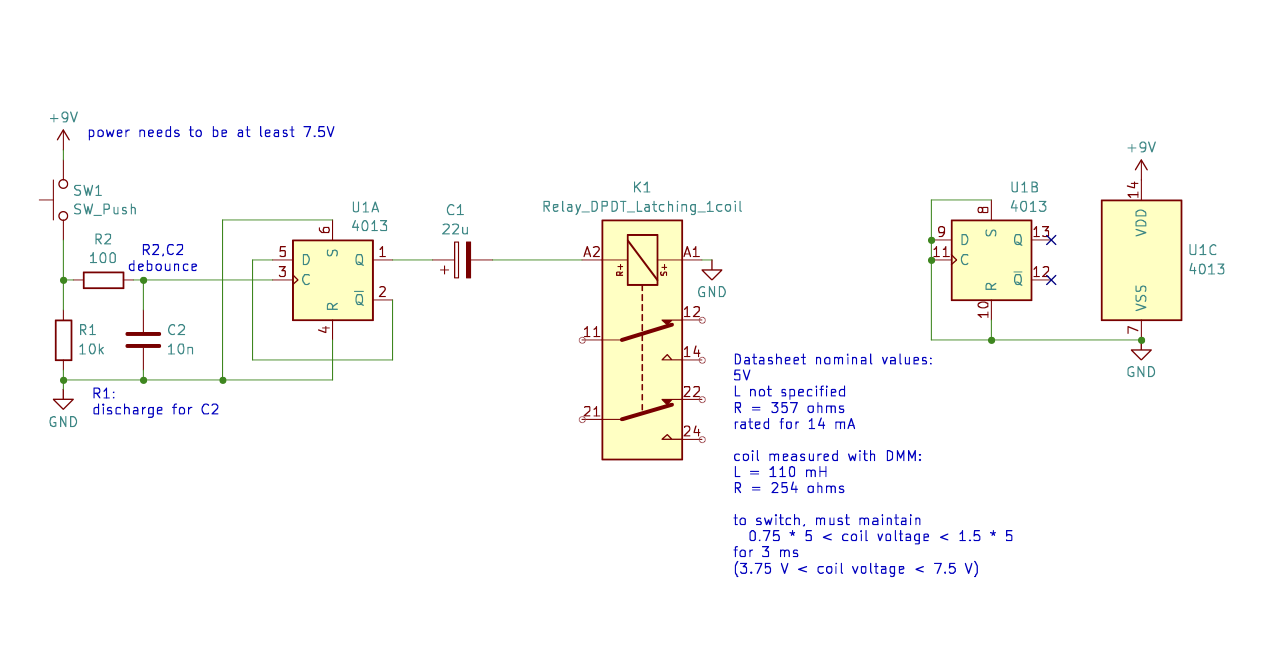 Schematic for testing the TQ2 latching relay.
SW1 toggles flip-flop U1 which causes capacitor C1 to charge or discharge through the relay coil. The coil “sees” an exponentially decaying pulse each time the flip-flop toggles.
Charging the cap causes a positive pulse and discharging the cap causes a negative pulse.
There are some gray areas with this simple circuit that eschews the clean pulses suggested by the datasheet. What value capacitance should C1 be? What power supply voltage do we use?
The relay datasheet says it needs to see at least 75% of the rated voltage (3.75 V in this case) for a maximum of 3 ms to trigger the state change, but it also says not to exceed 150% of the rated voltage (7.5 V in this case). We are also advised to keep the current under 14 mA.
To explore this further, I first did some analysis, then a breadboard bench test.
Analysis
In order to analyze the coil voltage, I used a DMM and measured the resistance of the coil as 254 ohms and the inductance of the coil as 110 millihenries. I left the value of the capacitor and the power supply voltage as parameters $C$ and $V$.
I modeled the CD4013 output as a unit step function scaled by the power supply voltage, $V u(t)$, in series with the capacitor $C$, a 254 ohm resistor (coil resistance) and a 110 millihenry inductor.
The goal was to find an expression for the voltage across the coil as a function of time, so I took the route of working in the complex frequency domain (s-domain) to solve for the coil current, and then return to the time domain to graph the function.
Transforming the circuit to the s-domain, Kirchhoff’s voltage law tells us the step function voltage must equal the sum of the series impedances times the current or
\[\frac{V}{\boldsymbol{s}} = \biggl(\frac{1}{C\boldsymbol{s}} + 254 + 100\boldsymbol{s}\cdot 10^{-3}\biggr) \boldsymbol{I}(\boldsymbol{s})\]and rearranging gives us the s-domain current as
\[\boldsymbol{I}(\boldsymbol{s}) = \frac{V}{0.11\boldsymbol{s}^2 + 254\boldsymbol{s}+1/C}\]To get back to the time domain, I typed the rational s-domain expression into WolframAlpha, prefixed with “inverse Laplace”, and it gave me
\[i(t) = \frac{0.00787402e^{-1154.55t}V \sinh \Biggl(1154.55 \sqrt{1-\frac{6.82001\cdot10^-{-6}}{C}} \Biggr)}{\sqrt{1-\frac{6.82001\cdot10^-{-6}}{C}}}\]The voltage across the coil is found by taking the derivative of the current (another task for the computer) and multiplying it by the inductance
\[v\_{coil} = L \frac{di}{dt} = 0.11\frac{di}{dt}\]Throwing all that into Desmos and setting $V=9$ and $C=22\cdot 10^{-6}$ gave me this graph:
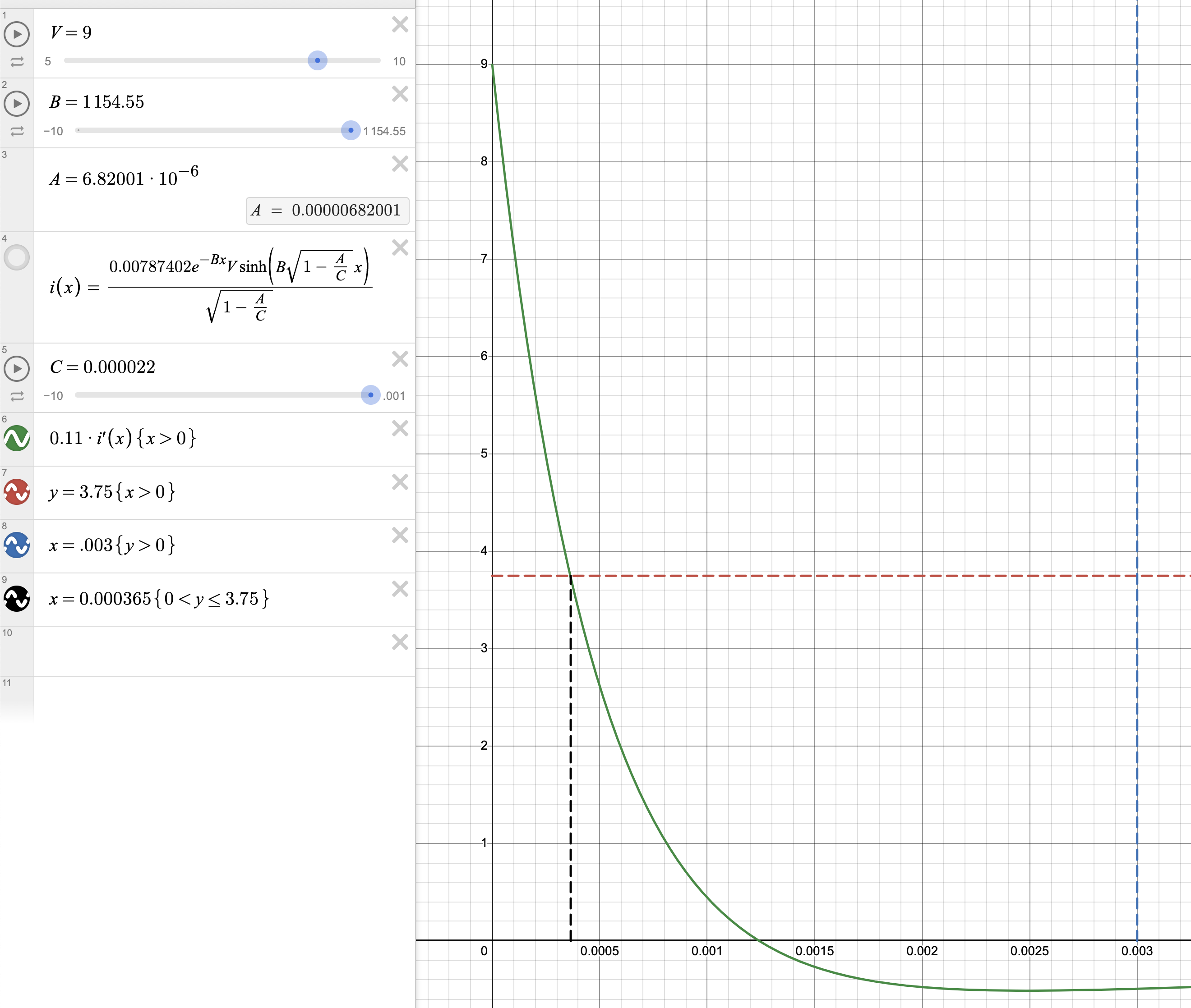 Screenshot of Desmos graph of coil voltage.
The coil voltage is the $y$ axis and time is the $x$ axis. The analysis predicts this simply won’t work: the 3 ms is the blue line and the coil voltage falls short of the 75% level after a mere 365 microseconds.
The maximum current is a bit high at 30 mA just past 1 ms. The coil is only rated for 14 mA.
Note the bit of overshoot as the $RLC$ circuit is a bit underdamped. Increasing $C$ does remove the ringing, but the value becomes huge before improving the spec we are actually interested in, which is the time before the voltage dips below 3.75 V. Increasing $R$ seems to be ineffective at improving things as well.
While I wasn’t able to get the desired 3 ms above 3.75 V pulse time by playing with the parameters, the analysis was helpful to verify the general shape of the pulse and what to expect from varying parameters prior to the bench test.
Simulation
Throwing the circuit into the Falstad simulator yielded a much more optimistic result of plenty of 75% voltage, even with a 5 V supply, as shown in this screenshot:
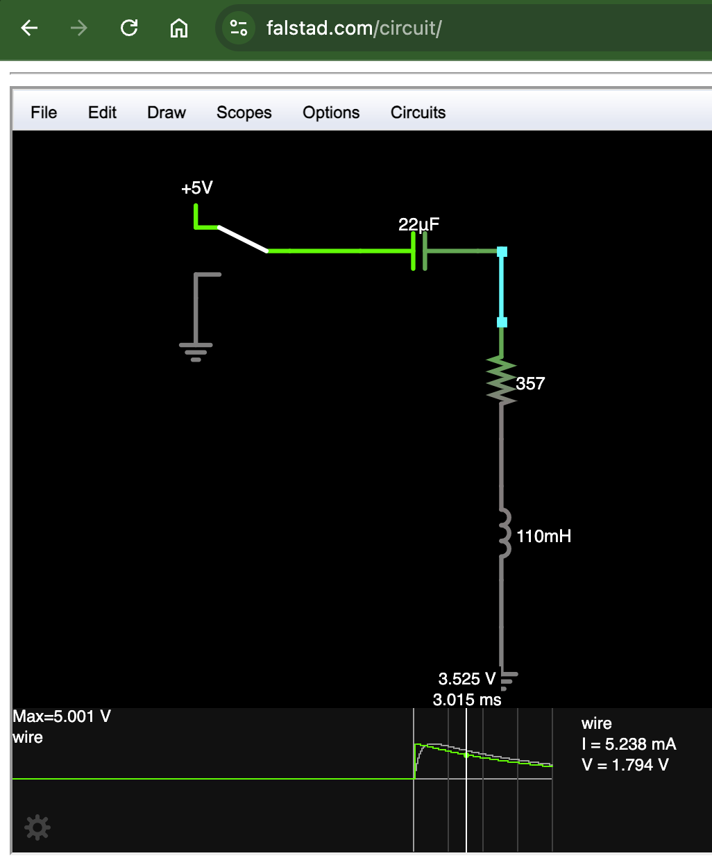 Screenshoot of Falstad circuit simulator.
Bench test
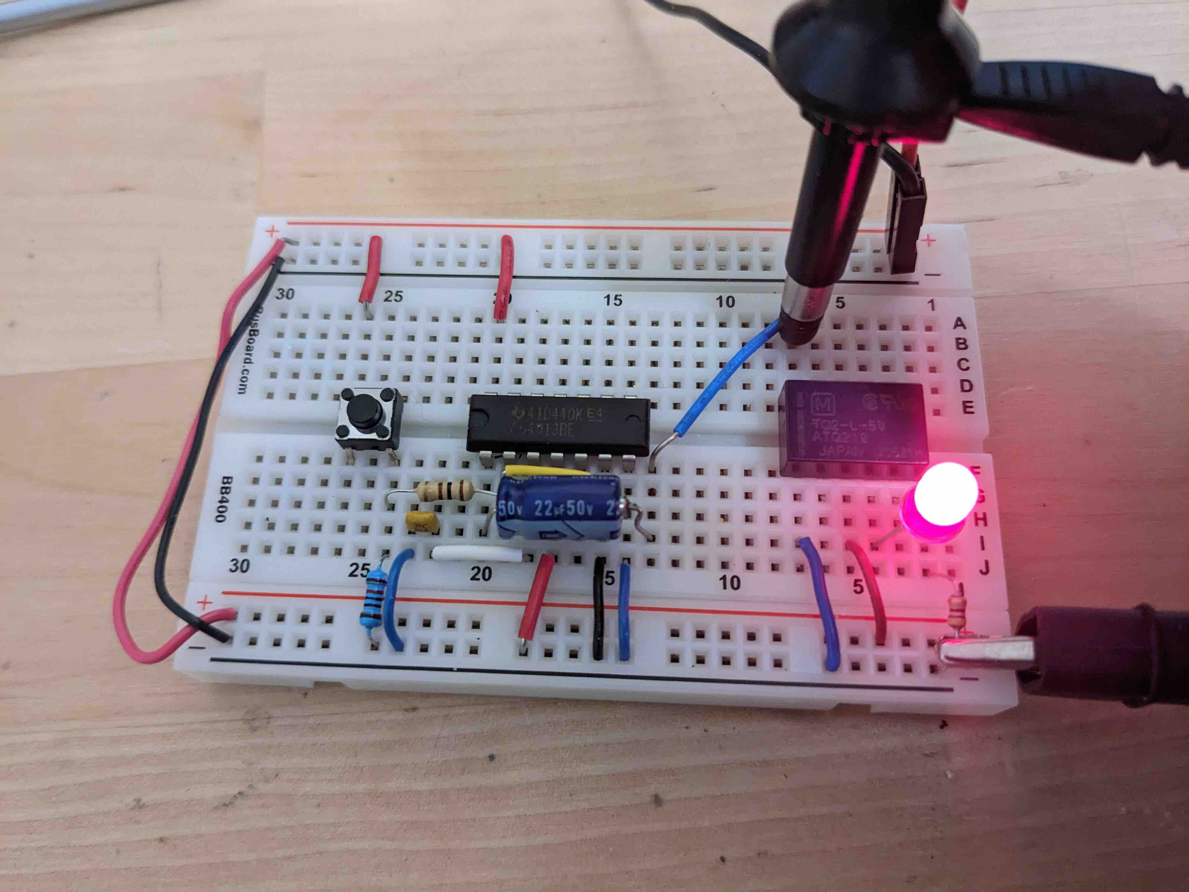 CD4013 and TQ2 ready to test. LED used to verify the relay was actually switching.
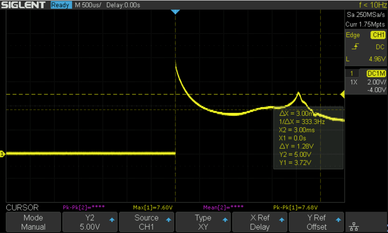 Oscilloscope screenshot of a relay toggle event.
The bench test was interesting. The power supply was set to 7.5 V, and the capacitor was 22 uF. The first curve dips below the 3.75 V line around 600 microseconds, fairly close to the Desmos graph, but afterwards it doesn’t shoot towards zero, behaving more like the simulator. There is a second bump in the curve, near 3 ms, presumably an effect of the relay switching states. The datasheet says the maximum pulse time needed is 3 ms, so it follows that the actual switch event occurs before 3 ms.
Playing around with it, the power supply has to be a minimum of 7.5 V or the relay fails to toggle. 22 uF seems to be a good minimum value to use; lower and it fails to function, higher doesn’t seem to improve the performance. Just out of curiosity I also tried adding some extra series resistance, but the analysis predicted that wouldn’t help and the bench test confirmed it (the coil needs current to work, so limiting the current just forces you to make something else bigger, i.e. $V$ or $C$).
The peak voltage and current are high and make me worry about early failure of the relay, but it performed quite reliably on the bench.
Perhaps for further testing I can drive it with an oscillator and let it run, switching for hours or days on end. Something to think about…
PCB design
Since the schematic was already in KiCad, here’s a 3D render of a breadboard adapter PCB for the relay:
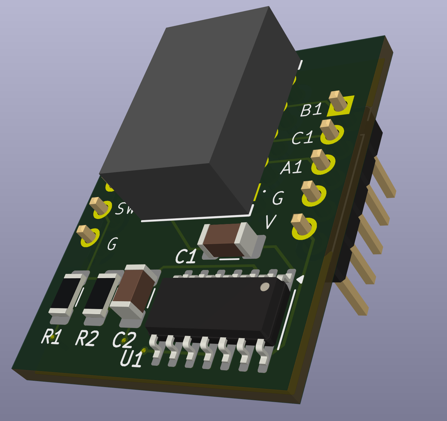 3D render of PCB to adapt relay to a breadboard.
Another idea would be to add a hole for a momentary footswitch and make it a close to the typical 3PDT “true bypass” switch footprint as possible. The LED could be powered directly from the CD4013 leaving the two switch poles free for completely switching the input and output jacks.
