
EMT 250
EMT 250 programming instructions
Historical background
The EMT 250 was the first commercially available digital reverberation unit.1 EMT was an established industry leader in electromechanical reverberation units which created artificial reverb by driving large metal plates with source audio and returning to the user the vibrations of the plate turned back into electric signals. The devices were very large and sensitive to their surroundings (picking up unwanted external vibrations).
EMT entered the digital realm in 1972 with the EMT 440 Electronic Delay System.2 The idea was to add a small “pre-delay” (30-60 ms) to give the illusion of reverberation in a large acoustic space. This “pre-delay” is significant to the 250, which has a similar function baked in and it runs independently from the digital computer.
EMT must have had good foresight that computer generated reverberation effects were on the horizon as they managed to be first to market with the EMT 250. There had been research into digital reverb at Bell Labs, but the efforts were limited to offline processing: audio data was slowly rendered with the reverberation effect. A few seconds of audio might take hours to render. Dr. Barry Blesser of MIT was interested in processing digital reverberation in real-time and worked on the EMT design with computer manufacturer Ralph Zaorski, co-founder of Dynatronics and Karlo Baeder of EMT.3 The designers required a computer that would calculate fast like a large general purpose computer but also be specialized for audio processing in order to reduce costs. Such a system did not exist yet.4
The EMT 250 used a computer designed by Dynatronics, algorithms designed by Dr. Barry Blesser, and analog conversion hardware provided by EMT.
Starting the puzzle
My research focused on the Dynatronics computer. While servicing an EMT 250 that needed some replacement memory and pre-delay line ICs, I became intrigued by the lack of information available on the digital computer. There were five 26-pin headers labeled “Test” in the schematics that seemed very interesting. In my research, I came across some C code billed as an EMT 250 ROM parsing utility. This was probably how I got it in my head to dump the ROM contents. I emailed the author of the utility to see what they were up to, but my email was never answered. I also emailed Dr. Barry Blesser asking if he has any notes on the programming of the EMT 250. Dr. Blesser answered my email, but, unfortunately, he had no notes to share.
Reading the ROM
The test connections allowed for observation of the ROM contents by connecting to two of the test pin headers,
but this meant reading the instructions in their execution order, which is a bit messy.
I chose to remove each ROM one-by-one and read the contents to my desktop computer using an Arduino as an interface.
I wired up 9 Arduino pins as address outputs, and 4 pins as data inputs.
The sketch looped over each address once and transmitted the result over USB to a desktop computer; one hex nibble,
in ASCII, per ROM, per address.
I chose to store my readings as ASCII characters instead of raw binary.
I felt that would make it more portable and easier to work with.
The standard Unix utility paste was helpful to combine all the ROM dumps back into 32 bit words.
Simply parsing the ROM with the utility I had found did not prove to be very insightful. The utility expanded each machine instruction, but I found the resulting wide format (276 columns in verbose mode, 238 columns in non-verbose mode) to be too much for my brain to absorb.
I set out to write my own parser in the hopes I could eventually generate something more like assembly or even C code from the machine code. I felt like a had a bit of a chicken-and-egg problem since I would need more insights to write the parser, but I was trying to write the parser to get more insights. I would need to spend more time reading the schematics and playing with the hardware to advance my understanding.
Stepping the computer
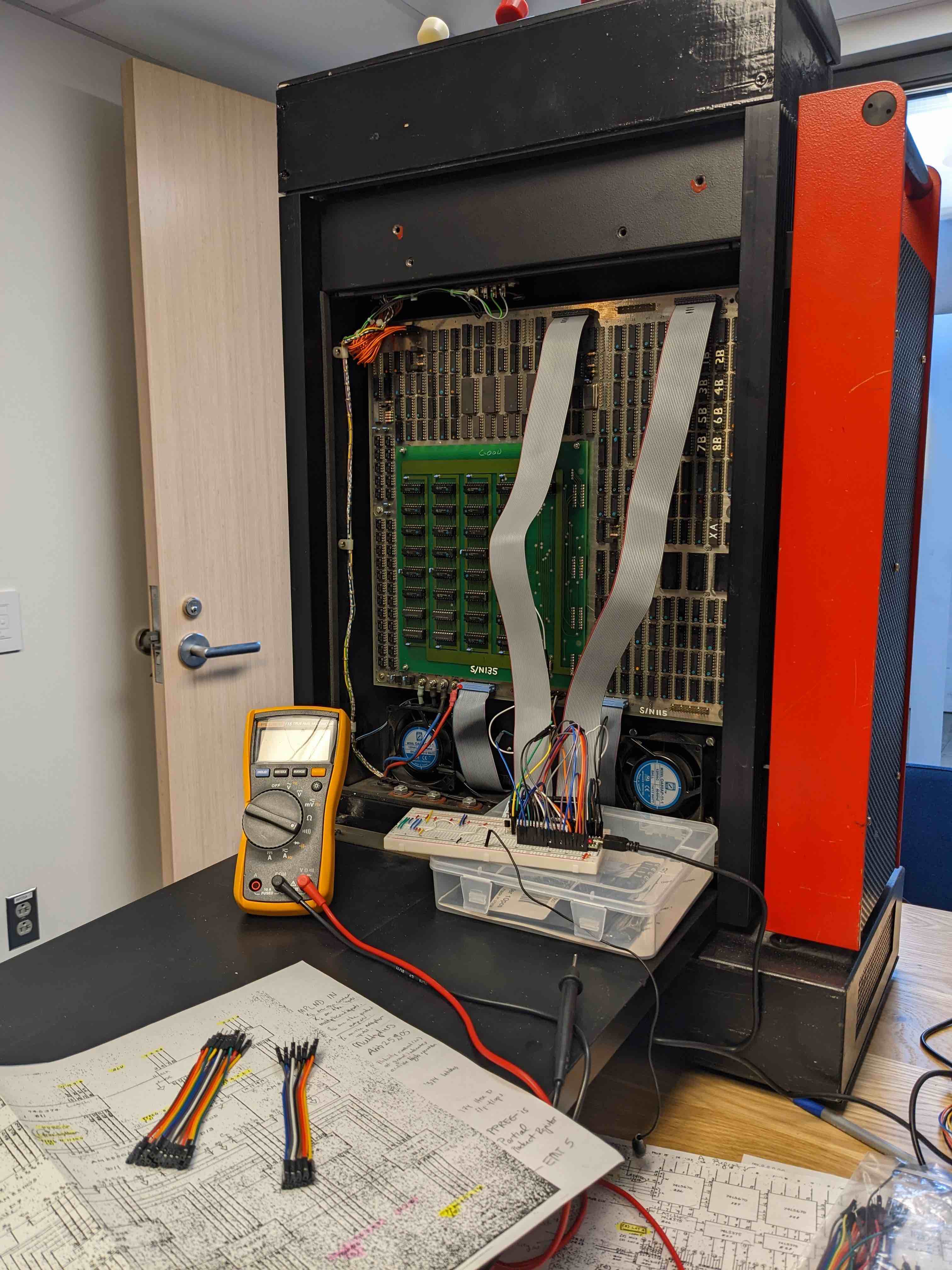
I was still very curious about the test connections, so I began interfacing with them in earnest. Pin header “TEST A” included two very useful taps into the computer: “4 MHZ CLK OUT” and “CLK CONT”. “CLK CONT” tapped right into the 4 MHz clock for advancing the instructions and much of the computer system. By bringing “CLK CONT” low, the system could be halted. I guessed that the “4 MHZ CLK OUT” was provided to work in concert with the “CLK CONT”. All I needed was a fast enough Arduino and a transistor to short the “CLK CONT” line. To make sure the Arduino was plenty fast I used a Teensy 4.1 which clocks at 600 MHz and included a nanosecond scale delay function. Using 74 logic chips would have probably worked as well to keep a vintage flavor to the project, but I did not want to spend time designing anything out of logic chips.
To track where I was in the execution, I needed to monitor the program counter (PC). “TEST D” included the 8-bit program counter, but would also need the 9th bit, which briefly eluded me. I came up with some wild theories like maybe all the programs ran in 256 lines and there was test code or some other easter egg hidden in the other 256. Eventually I figured out the 9th bit of the ROM address was simply wired to the “REV” push button allowing the programmers to split the ROM address space into a bank for the reverb program and a bank for the rest. The 9th address bit is exposed on the “CONTROL” pin header, along with all the other wires going to the control panel. I did not ever fully remove the computer so I opted to grab the 9th bit from its pull-up resistor which was easy to spot. Once all 9 bits were connected to the Arduino, I could record the PC as I stepped.
I added a simple serial command interface to control the Arduino stepper from my desktop computer. The available commands are
halt: stop the clockcont: run the clockstep: advance machine by 1 instruction (runs clock until the “not clock” line goes high)addr: print the current addressuntil [n]: run until address n is observed
With these commands it was pretty easy to trace the execution and at least see how the different programs were organized within the ROM. At this point I still didn’t grasp exactly how the computer was jumping around or performing any DSP.
As I had more sessions with the stepper hardware, I used input pins to monitor what the test connections had to offer:
- ALU
- PPREG (partial product register)
- multiplier inputs
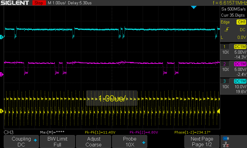
Various other hardware signal lines I observed with my oscilloscope. This was necessary as many of the signals are pulses that do not just “freeze” when you stop the clock. I used this to verify when the multiplier was loaded or a skip command executed, etc.
By printing out the results of the ALU along with the PC, I had a good map to follow as I returned to parsing the machine code.
Reading the schematics
A ‘181 based minicomputer
My initial reading of the computer schematics was difficult as I had no experience with this era of computer hardware. The EMT 250 does not have a microprocessor. The CPU is built around the 74181 ALU, which is a 4-bit dedicated ALU IC. The EMT 250 uses 4 of the 74181 ICs to create a 16-bit ALU. That was easy enough to figure out, but then I had to figure out how everything around the ALU worked both individually and as a system. It was that next leap in understanding that left me stumped for some time. As part of my 74181 research, I came across Ken Shirriff’s analysis of the IC. I reached out to Ken, and he was very generous and willing to offer me some quick assistance. He gave me just the overview of the computer I needed to push forward.
I also had contemporaneous papers written by Dr. Barry Blesser and Ralph Zaorski to provide a general sense of the target architecture and how the DSP would would.3 4
My notes for the technical details of the machine are posted on the EMT 250 technical info page.
Mapping it out
My observations of the programs in bank B revealed my first real “hook” into deciphering the operation of the machine. All of the machines shared a common path of code which included an obvious “do nothing” loop to waste time and an obvious lookup table that let the programs jump to the correct address after checking the state of the control panel. Since I had a pretty good idea those behaviors were happening, I kept checking my guesses as to how the instructions worked against those areas of the code.
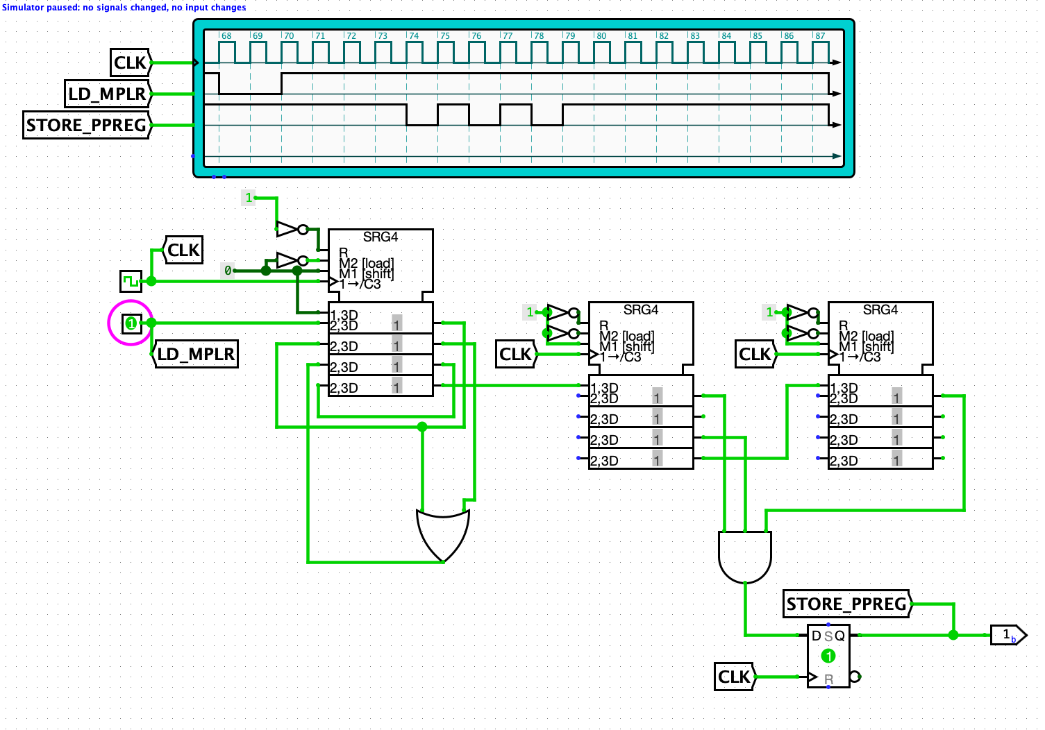
Logic level simulation
Logisim-evolution was helpful in visualizing and checking some of the hardware, but it was limited primarily due to questionable use of the 74 series flip flops! 74 series flip flops have an unstable state that is heavily used in this computer and Logisim was unhappy if I attempted to simulate them as shown in the schematic. The computer also uses “transparent” latches and registers that can be read from one address while writing to another. These components, which operate between clock cycles are not easy to simulate in Logisim, so I was only able to play with small snippets of the circuits that way.
Building a simulator
I was looking to see if anyone at NYU might be interested at studying the computer, and I ended up getting guidance from Professor Jeff Epstein. After discussing my interest in researching how to program the machine, Professor Epstein suggested I build a simulator and see what else the EMT 250 is capable of besides processing audio. The initial goal would be to load the simulator with the ROM dump
First I documented the EMT 250 instructions and then modeled each major component of the computer architecture as a C++ class. The initial design went pretty quickly and I was quite pleased when the ROM appears to run around as expected without much trouble. Upon closer inspection the initial runs were not right at all as I had baked all my misconceptions and some typos into the code.
The first major misconception I needed to unravel was the nature of the “skip” operation. For some reason I had tried really hard to erroneously convince myself that “skip” and “jump” were the same idea and I kept expecting everything labeled “skip” to be directly related to manipulating the program counter. I finally dispelled that idea by watching the “skip” and “load PC” signals on the oscilloscope and convinced myself they were independent.
The second major issue I had was a silly typo I had made when using the C bit shift operators and screwed up my checks for multiplication.
There remains a general issue with converting how math works in the EMT 250 with math in my simulator. I am not yet trying to process audio in real-time. The simulator generates a sine table and feeds the simulated machine generated samples as needed. The results of one run are shown below to demonstrate just how incorrect my math is currently.

I am almost certain my current problem lies in the simulator’s multiplier RAM which carries two extra important bits of info I neglected to implement!
Next steps
After the simulator is emulating the behavior reasonable well, I would like to try to write new programs for it. I wanted to test the limits of its general purpose capabilities. It lacks an obvious way to hook up to a terminal, but I suspect something could be arranged. The D/A output could provide a 12-bit output data bus for ASCII data that some kind of adapter board could send to a display. Similarly, the A/D input could potentially be hijacked to take in ASCII input.
Hardware test interface
I did not design an interface for all the test pin headers, but this is something that would be useful for servicing an EMT 250. Beyond the pin headers, an interface for the ROM sockets to a desktop computer would allow execution of test code. I imagine the test code could try various instructions and the ALU, partial product register, and D/A results could all be transmitted and validated on the desktop computer for a quick assessment of a troubled EMT 250.
-
A Step into a New Dimension: EMT 250 Electronic Reverberator Unit, EMT Courier, June 1976, Franz Vertiriebsgesellschaft m.b.H. ↩
-
A Brief Chronicle of EMT Artificial Reverberation, EMT Courier, July 1985, EMT-Franz GMBH ↩
-
Blesser et al, A Real-Time Digital Computer for Simulating Audio Systems, Journal of the Audio Engineering Society, March 1975 ↩ ↩2